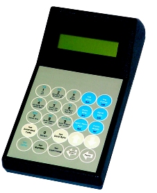
| IH5600 - PRU
256 PROGRAMMER & CONTROLLER |
 |
Features
- Transmits and Receives both standard as
extended X10 commands
- Displays noise level on the power line
- Displays signal level on the power line
- Can log noise and signal levels over 24h period
- Auto transmit mode for system testing
- Adjustable transmit voltage in 33,3 mV increments
- Time/Date (24h format)
- Selectable 0°, 30°, 60°, 90°, 120°, 150° transmit pulse
- Shows received X10 packets as one frame or two frames: can be used to determine whether signal is repeated
or original
- Can be used as P1 test transmitter when combined with the Marmitek XPTR test receiver (Art.No. 09103)
|
Use
& Applications
• Programming tool for Marmitek MicroModules
• Display signal strength on line from other transmitters and two way receivers
• Use to test potential installation sites for possible installation problems
• Pinpoint loads to be filtered by logging power grid noise levels (user defined time periods up to 24 hours)
Technical information
- Supply voltage : 120 to 277 VAC (+/- 10%)
- Frequency : 50 Hz
- Current draw : 270mA at 240VAC/50Hz
- Receive Parameters : The PRU256 will accept power line carrier
transmission signals with minimum strength of 25mV peak to peak. The
carrier frequency of this signal will be 120 kHz ± 4kHz. The pulse width
will be 1ms ± 10% and occur no later than 200ms after the zero crossing
of the main voltage.
- Transmit Parameters: The PRU256 will output power line carrier
transmission signals with a minimum of 6V peak to peak strength into
a power line with a 5 Ohm load attached. The carrier frequency will
be 120kHz ± 1kHz. The transmission pulse will be 1ms ± 10% and will
start no later than 200ms after the zero crossing of the mains voltage
and when enabled an additional pulse will be transmitted no later than
200ms after the 30° point of the half wave.
- Transmit Locations: All transmission locations (0°, 30°, 60°,
90°, 120° & 150°) can be individually activated or deactivated through
the SETUP menu.
NOTE: More than four activated transmit locations may deliver unsteady transmit level results.
NOTE: The 0° transmit location must remain enabled if the automatic level adjustment is to remain
active. If the 0° transmission is disabled, the circuit will always adjust to maximum level.
- Transmit level: The level of the powerline carrier transmissions can
be adjusted through the setup menu. When the level is set from 0 to
150 the Automatic level adjustment will be active. This will readjust
the signal level for line loading conditions. The maximum adjustable
level is 5V peak to peak (level settings of 150). Any setting above
this will result in a maximum output (>/= 6V peak to peak).
- Display : 16 Character x 2 Row LCD, Bottom viewing angle. Contrast
adjustment is possible with adjustment potentiometer on the right side
of case.
Download data sheet
|
